3D Scene Creation
3D Reconstruction from Single Moving Camera
Scene reconstruction systems are developed to assist autonomous machines with self awareness, navigation and completion of tasks. Unlike a stereo system, which uses two cameras positioned at a set distance apart with a set orientation, a monocular system utilized only one camera and relied on the camera movement to reconstruct a scene. The project presented below describes a monocular vision system attached to a flying unmanned aerial system (UAS) or a roaming unmanned ground vehicle (UGV) that without the use of GPS is able to construct a 3D model of the scene surrounding the vehicle in real time.
Humans subconsciously utilize their eyes to analyze a scene. When driving a car down a street or walking in a hallway, we can easily determine when it is time to make a turn based on what we observe. But how do we know that a turn is coming up? And more importantly, how can we accurately determine the distance to travel and the speed needed to avoid collisions with walls and pedestrians. The system we are constructing contains solutions to these questions as well as many others.
First, the vehicle must be able to "see" where it is and its immediate surroundings. Second, the vehicle needs to determine how to move and avoid collisions with potential obstacles. As it travels through the unknown environment, the vehicle needs to "remember" where it has been and generates a model of everything it sees as it explores.
Applications for this technology include reconstructing an accurate 3D model of a UAS/UGV environment to support search and rescue, emergency response, situational awareness enhancement for first responders, law enforcement search activity, surveying and numerous military operation.
The reconstruction process begins by processing each input frame and extracting the speeded-up, robust features from the image. Depending on the resolution, an image can contain over 10,000 feature points. Points, each described by 128 elements, vary in size and orientation.
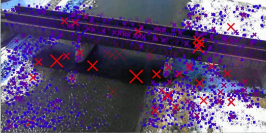
Next, we determine which points correspond with one another from consecutive frames. By matching points, we are able to determine how much the feature has traveled in an image (measured in pixels). This measure, called a feature's disparity, is used to determine the feature's depth from the camera plane.
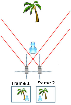
The image below helps illustrate the principal of this project. Disparities of objects close to the camera plane appear much longer then those of objects far away.
As a result each feature point is associated with a depth value. Each point derives a value (X,Y) in relation to the camera using a focal length analysis. The X-component is determined from the disparity to depth transformation. After a filtering process to eliminate unwanted noise values, we plot the (X,Y,Z) values to obtain a colorful point cloud of a scene. This point cloud creates surfaces and textures that gives the reconstructed 3D model a "real-world" feel.
3D Reconstruction Demonstrations
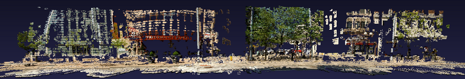
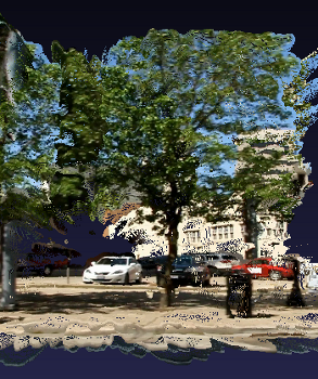
3D Reconstruction Model of Scene
|
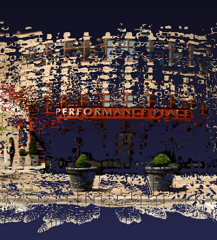
Details on Buildings |
Details on Cars and Trees |
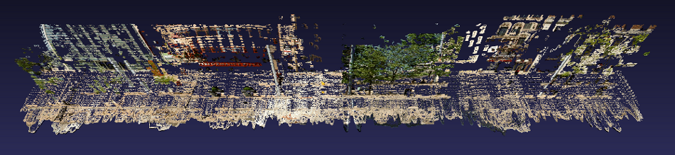
Top View of Point Cloud Model